Frequently Asked Questions

While Cryo-EM is better able to capture multiple protein conformations than some other structural biology techniques, if the sample is poorly folded, aggregated or otherwise disordered, data quality will be impacted. We therefore recommend ensuring your protein is in an environment that maximises its stability. Protein stability screens and assays are available from a variety of suppliers and the theory behind them is described in:

The best sample support depends on the exact characteristics of your sample, but we can provide some advice on what has worked previously. Our most popular holey carbon support for biological samples is QUANTIFOIL® Carbon R 1.2/1.3 (used in approximately 60% of published cryo-EM studies using QUANTIFOIL® grids). This film offers holes small enough to provide thin ice and good support for biological samples but large enough to ensure an adequate number of particles for analysis. However, there are some additional considerations that might make an alternative holey support more appropriate:

  • If you have larger particles such as viruses or multi protein complexes, then a slightly larger hole such as R2/1 or R 2/2 may be more appropriate.
  • Choosing a slightly larger hole (such as R 2/1 or R 2/2) can allow faster data collection by taking multiple shots in a single hole before stage-shift and refocus.
  • Small hole sizes (R 0.6/1) form the thinnest ice layers and can be useful for membrane proteins or smaller particles requiring more support and minimal background. 
  • If sample dispersal is not optimal, changing grid geometry can sometimes help. Trying a MultiA grid (which has a range of hole sizes on a single grid) is one way to find out if this will help with your sample.
  • If your particle can adopt a range of sizes, such as a membrane protein embedded in a liposome, then MultiA QUANTIFOIL® Holey Carbon supports or lacey carbon grids will maximize the number of useful holes on a single grid. MultiA grids are easier to use with automated collection software than lacey carbon, as the holes have a regular pattern.

Confused about how holey support naming conventions work? You can find an explanation here.

UltrAuFoil® Ultra-stable Gold supports give better 3D reconstructions from less data by reducing the movement of frozen specimens during imaging. Any sample can benefit from improved data quality from UltrAuFoil® supports, but they are particularly recommended for:

  • Small proteins and membrane proteins where beam-induced motion can have a particularly significant effect.
  • High-throughput data collection: using every frame in a movie stack together with reduced strain due to foil crinkling means less data is required to reach atomic resolution, increasing throughput.

If you'd like to know more about UltrAuFoil® Holey Gold supports, and how to optimize your data collection conditions when using them, check out our UltrAuFoil FAQ here.

Copper grids are the traditional choice for cryo-EM, because they are robust, highly conducting and radiation hard, so do not build up sample-damaging charge or become unstable in the beam. However, copper can be cytotoxic, so many researchers with biological samples prefer gold grids, which have the same advantages for data collection as copper, but are also biocompatible. 

A square 300 mesh grid is a good first choice, providing a balance between 200 mesh grids which have fewer bars to obstruct the open viewing area but are more easily damaged during handling, and finer meshes which are more robust and provide additional support but reduce the open viewing area size. 

Want to know how grid mesh sizes work? Read our guide here.

The bars of the grid obstruct a large portion of the open viewing area when the grid is tilted, for this reason we recommend using grids with the largest open viewing area:bar ratios. Two hundred mesh grids are the best initial choice, but if you find the bars are still obstructing your image, there are a couple of options:

  • Rectangular grids (100 x 400) with the long dimension aligned with the tilt axis offer the largest open viewing area, but do require you to align the grid accurately when loading.
  • Hexagonal grids (available in 100, 200, 300 and 400 mesh) offer the highest open viewing area for a given mesh size while maintaining grid strength. Hexagonal grids do not need to be aligned.

You can learn more about alternative grid meshes and materials in our base grid guide here. If you would like a quotation for one of these special formats, please contact us.

The hydrophilicity and thus wetting properties of both carbon film and gold foil supports can be significantly improved  by plasma cleaning the grids prior to use. Particle distribution may also be improved by altering grid surface characteristics by the addition of volatiles such as amylamine during plasma-cleaning.

Sample supports can be contaminated during storage for a wide range of reasons, including simply gathering dust. While it is not required, you may wish to consider washing your sample supports in organic solvent prior to use, a protocol is provided. We advise against washing any sample support with an additional ultrathin layer of carbon prior to use. 

There are several ways you can ask the wider cryo-EM community for suggestions and advice about sample preparation issues:

  • The ccp-em and 3DEM message boards: though these boards are focussed on computing issues, subscribers are also happy to help with sample preparation issues.
  • Many cryo-electron microscopists are active on twitter, and this can be a great place to start a discussion on sample preparation.
  • The Discord CryoEMCafe server has a sample prep channel which provides excellent support and advice about these issues. 

The most important choice when growing cells is to use biocompatible gold or molybdenum rather than standard copper.

If you would like further advice on optimizing sample supports for on-grid cell growth, then please contact us.

Whenever a process involves manual handling of the grids, there will be a danger that the grid surface is damaged or the grid itself bent, especially with 200 mesh grids popular for tomography, and with more pliable gold grids. For this reason we would recommend avoiding manual handling wherever possible. A grid holder such as that described in Fäßler et al. BioRxiv (2020) can reduce manual handling requirements. These devices allow hands-free transfer between different solutions without physically touching the grids and so significantly reduce the number of grids lost to handling errors.

Helical reconstruction works best when there is no strain or bending in the fibrils being studied. Fibrils will necessarily experience some strain as they cross the boundary between hole and carbon support. We therefore would suggest using larger hole sizes such as R 3.5/1 to maximise the length of fibril unaffected by the hole/support boundary. Square film geometries offer the largest ratio of hole to carbon support, and some researchers have been successful using square geometries to study fibrils (for example: Lee et alNat Commun 11:5735, 2020).

Many proteins adsorb strongly onto carbon surfaces, and one common reason for only a few particles appearing in the film holes can be that much of the sample has adsorbed onto the carbon support itself. A common way to solve this issue is to add an ultrathin continuous layer of carbon (UTC; normally 2 nm thick) on top of the holey carbon support. We can add a UTC to any support purchased from Quantifoil. If you are interested please contact us.

These layers are too thin to cause a significant increase in the image background but allow the protein to adsorb across the whole support and therefore increase the concentration of particles available to image in the holes.

Reducing preferred orientations requires changing the way a protein interacts with the grid, there are a number of ways in which this can be accomplished. They can be tried both individually and in combination:

  • Complexing your biomolecular with an  antibody or antibody derivitive (Uchański et al (2021). Nature Methods 18: 60-68), adding a large protein tag, or simply screening grids for your protein with and without a His-tag (Bromberg et al (2020). bioRxiv 10.1101/2020.09.22.309005).
  • Screen grids in a range of pH, buffers, ionic strength and small molecular additives: by changing the protein buffer conditions, you alter the protein surface charge distribution and change the way it interacts with the grid. Adding a small amount of detergent may change protein interaction with the air-water interface and reduce preferred orientations, CHAPSO has been particularly recommended for this purpose (Chen et al (2019). J. Struct. Biol. 1: 100005)
  • By changing your sample support, you change the protein's interaction with it. This can include moving from QUANTIFOIL® (holey Carbon film) to UltrAuFoil® (holey Gold film) supports or by changing the film geometry and grid metal. You can also change the grid surface characteristics by altering your plasma-cleaning protocol, or altering the carbon surface by adding volatile additives such as amylamine to the plasma chamber. 
  • Highly recommended: additional layer of Ultrathin Carbon (Rawson et al (2015). Structure 23: 461-471). The continuous additional layer adsorbs your protein, drawing it away from the air-water interface, adsorption to which is often a cause of preferred orientation. We can supply most of our grids with an additional layer of ultrathin carbon, with your choice of thickness from ~2 nm to 10 nm. Two nanometres of carbon is virtually electron transparent and adds very little to your image background, so that data quality does not suffer from this method.
  • Tilted datasets are highly recommended to solve preferred orientation issues (Tan et al (2017). Nat Methods 14: 793-796). When collecting tilted data, it is important to remember that the bars and support film are more intrusive when imaged at an angle, this can be reduced by opting for wider mesh sizes. For maximum open viewing area,  hexagonal grids, or a 100 x 400 rectangular mesh with the short dimension aligned with the tilt axis can be selected. It may also be useful to try a larger hole geometry such as R 2/2 or our MultiA film geometry, with the eliptical holes aligned with the tilt axis.
  • Rapid freezing using automated sample preparation instruments, such as chameleon from SPT Labtech, may also reduce preferred orientations as vitrification occurs too rapidly for the particles to orient systematically.

Many proteins will adsorb onto the air-water interface: by some estimates as many as 90% of particles may position themselves at this interface (D'Imprima et al (2019). eLife 8: e42747). The hydrophobic nature of this interface means that proteins located at it may unfold, aggregate or denature, at least partially, and this has detrimental effects on the quality of data that can be obtained from these samples. There are several ways to remove particles from the interface:

  • Adding a protein-friendly surfactant to block access to the interface. CHAPSO is often suggested as a good option in this circumstance (Chen et al (2019). J. Struct. Biol. 1: 100005).
  • Minimise interaction time by ultrafast blotting and vitrification with a sample preparation instrument, such as SPT Labtech's chameleon.
  • Sequester your protein away from the air-water interface by adsorbing it onto a continuous additional layer of Ultrathin Carbon (Rawson et al (2015). Structure 23: 461-471). We can supply most of our grids with an additional layer of ultrathin Carbon, with your choice of thickness from ~2 nm to 10 nm. Two nanometres of carbon is virtually electron transparent and adds very little to your image background, so that data quality does not suffer from this method.
  • The simplest way to alter the surface chemistry of a grid is to add a vial of a volatile organic, such as amylamine, into the chamber when plasma cleaning. The plasma-cleaning exposes active carbon surface to which the amylamine or similar molecule can then attach. 
  • Both gold and carbon holey support films can be PEGylated as described in Toro-Nahuelpan et al Nat Meth 17: 50-54 (2020) and Engel et al J Micromech Microeng 29: 115018 (2019). PEGylated grid surfaces can be extensively modified using established chemical reactions, allowing you to change the surface properties or even add affinity tags for proteins.

Plasma cleaning is an effective sterilising method, and you many not require any additional treatment prior to using them for cell growth.

However, should you wish to do so, you can sterilise your Quantifoil grids using 70% ethanol. Methods for doing so are provided as part of the on-grid cell growth protocols in these two publications:

1) Hampton et al. Correlated fluorescence microscopy and cryo-electron tomography of virus-infected or transfected mammalian cells. Nature Protocols 12: 150-167 (2017)

2) Engel et al. Micropatterning EM grids for cryo-electron tomography of cells. Protocols.io 

As always, Cryo-EM grids should always be handled as little as possible and with care to avoid damaging the film. It may be worth considering a grid holder to avoid unnecessary manual handling as described in Fäßler et al. BioRxiv (202).

The film geometries all have a letter and two numbers in their names.

  • If the film name starts with "R" the holes are round, when it starts with an "S" the holes are square.
  • The first number provides the diameter of the hole and the second is the spacing between holes, both in microns. The larger the first number, the larger the holes, and the larger the second number the more carbon is present between holes.
  • In some cases, the "periodicity" of the film is referred to, this is the sum of the hole diameter and the spacing (the first and second numbers) and is the distance between the start of one hole and the start of the next.

Some examples are provided below for clarity:

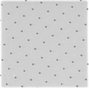
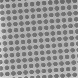
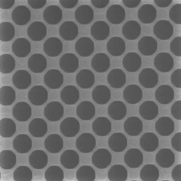
Geometry Description Hole (μm) Image
Shape   Size Spacing Periodicity
R 1/4 Round 1 4 5 quantifoil circular r1-4_sem-crop
R 2/1 Round 2 1 3 quantifoil circular r2-1_sem-crop
R 3.5/1 Round 3.5 1 4.5 quantifoil circular r35-1_sem-crop
S 7/2 Square 7 2 9 S7-2-crop-small


While we strive to ensure that our holey support films match the description provided, there can be some slight variation in hole size and spacing, though the overall periodicity (hole size+spacing) is constant. This variation should be no more than ±0.2 μm.

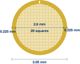
The mesh size for a grid is simply the number squares in one inch. Thus 200 mesh (with 200 squares in one inch) has a larger open viewing area than 300 mesh (with 300 squares in one inch). Electron microscopy grids are normally 3.05 mm in diameter, with a 0.225 mm rim. This leaves a 2.6 mm (or 1/10 inch) diameter circle of mesh, meaning that 200 mesh grids have 20 squares in each direction, 300 mesh have 30 squares and so on.

Example: 200 mesh grid dimensions

grid-dimensions


Sample supports are easily damaged and manual handling should be kept to a minimum. When handled we recommend using high-precision, extra-fine tweezers (style 5) available from all good electron microscopy suppliers. Grids should be handled only at the edge, away from the holes and with extreme care to avoid damage.

If your sample supports are still in the original box from Quantifoil, please see our page here showing how the grids are packed. Sample supports purchased in 50- and 100- packs are placed in the box with the holey carbon support facing the middle of the box. 10- and 25-grid packs have the carbon-coated side facing the side of the box with numbers. 

If you have removed the grids from the box and are no longer sure which side is carbon coated, then inspection under a microscope will quickly reveal which side has the carbon coat. As illustrated in this video (with thanks to Prof Grant Jensen, CalTech University), slowly rotating the grid will reveal that the carbon-coated side has a silvery-grey film when illuminated at an angle, while the uncoated side of the grid retains a copper colour at all angles.

If you have chosen copper/rhodium grids, the carbon-coat will be on the copper side, rather than the grey-coloured rhodium side, unless you have requested otherwise.

QUANTIFOIL® Holey Carbon support films are 10-12 nm thick, while Holey Gold films are around 50 nm thick (approximately the diameter of a single gold grain).

The thickness of the metal grid on which our gold and carbon films are supported depends on the size of grid mesh: higher mesh numbers (finer meshes) are thinner while lower mesh numbers (wider meshes) are thicker, with a 50 mesh grid being around 25 μm +/- 5 μm while a 600 mesh grid is 6 μm +/- 2 μm. 

While our current manufacturing processes are confidential, QUANTIFOIL® grids are described in Ermantraut et al. Perforated support foils with predefined hole size, shape and arrangement. Ultramicroscopy 74: 75-81 (1998). Dr Chris Russo has described the development of UltrAuFoil® grids in Passmore and Russo. Ultrastable gold substrates for electron cryomicroscopy. Science 346: 1377-80 (2014).

In order to reduce the risk of any cross-contamination between samples of interest, we do not recommend re-using QUANTIFOIL® Holey Carbon films or UltrAuFoil® Holey Gold supports.

Depending on the exact grid used, a single grid weighs in the range of 1-2 mg.

Using the same metal for both the grid and the foil improves the quality of your data because it reduces beam-induced motion caused by changes in the geometry and tension of the foil due to the elimination of the differential thermal contraction between grid and metal during plunge vitrification and sample irradiation. As discussed in Russo and Passmore, Science 346: 1377-1380 (2014) and Russo and Passmore. J. Struct. Biol. 193: 33-44 (2016).

Gold has several properties that make it ideal as a sample support in electron microscopy, including being conductive, nonoxidizing, radiation-hard.  In addition, it is does not interfere with the specimens you are studying as it is chemically inert and biocompatible, as described in Russo and Passmore, 2014 and 2016.

A foil thickness of 400-500 Å provides optimum data quality by balancing the need for the thinnest possible layer of ice with sufficient thickness of the gold foil to minimise beam-induced motion.

A thicker foil will not further reduce beam-induced motion, but risks degrading data quality due to thicker ice resulting in poor particle dispersion and increased background scatter. In contrast, a thinner foil might offer better particle dispersion due to the formation of a thinner layer of ice, but at <400 Å, the foil is thinner than the individual gold nano-particles it is made from and this increases beam-induced motion due to poorer conductance as the surface becomes uneven. See Russo and Passmore, 2014 and 2016 for further details.  

As for our other products, UltrAuFoils® should be stored in a grid storage box in a cool, dark, low-humidity environment. While there is no date of expiry for the UltrAuFoils® we generally recommend using them within two years.

UltrAuFoil® sample supports are ready to use straight from the box. However, as with all transmission electron microscopy grids, users may achieve better sample dispersion and improved wetting if the foils are made more hydrophillic. This can be achieved using standard glow discharge and plasma systems, as described here. UltrAuFoil grids particularly benefit from these treatments, as, lacking the more volatile carbon foil, they can be safely exposed to extended glow discharge or plasma treatment without risk of any surface degradation.

Because UltrAuFoil foils are Gold, and can therefore conduct, occasionally, depending on exact environmental conditions, they may charge in the plasma cleaner, and this may cause arcing between the grids. This effect can be mitigated by decreasing the current, and we recommend using no higher than 15 mA, or reducing the distance. In addition, supporting the grids on glass slides rather than metal holders can also reduce its occurence.

Yes. We are happy to supply UltrAuFoil® with an ultrathin carbon layer at a thickness of your choice (most commonly 2 nm, but 3, 5 and even 10 nm additional carbon layers are available on request). Alternatively, you may add an additional layer of amorphous carbon yourself: standard float transfer methods, as described in Passmore and Russo, 2016, are recommended to transfer thin films of carbon onto UltrAuFoils®.

Data collection can be carried out as you would for holey carbon foils with similar geometries. Thus, we recommend that the electron beam geometry is circularly symmetric beam and centered on the hole. The micrograph is taken at the centre of the hole. We would recommend including a small section of the support foil in each image, as this aids with focussing (see "How do I focus using UltrAuFoils®", below) 

Since there is no amorphous material in the gold support structure, Thon rings cannot be used to focus. Russo and Passmore, 2016, present a number of different options for focussing when using UltrAuFoils, but the two simplest are:

  1. Oscillate the beam tilt around 0°, and the plane for which the image shift is minimized is the in focus setting. This method is most useful for automated data collection.
  2. The micro-crystals of gold in the foil diffract elections, with the diffraction spots occurring in a ring around the crystal image at a distance related the lattice spacing of the gold crystals, as predicted by the Bragg equation, and the defocus. As the smallest lattice spacing of the Gold crystals gives rise to diffraction at a resolution of 2.35 Å, care should be taken to ensure that any objective aperture does not block electrons at the diffracted frequencies. This method is primarily recommended for manual data collection modes. 

We recommend using a calibration specimen to correct the stigmation and beam tilt prior to collecting data on UlrAuFoils®.

Yes, automated data collection has been successfully tested on UltrAuFoils® using beam tilt to focus.

No, they should be handled in the same way as traditional carbon foils, and are similarly robust. As with traditional carbon foils, care should be taken when handling the foils with tweezers and during plunge freezing, as if the foil is damaged in these processes, the stability of the support may be severely degraded. We recommend collecting data only from squares where the foil is uniform and intact.

In addition, the gold foil is not volatile when glow discharged or treated with plasma, so the grids may be subjected to far more extensive plasma treatments than standard carbon foils, without any risk of degrading the surface.

Dr Christopher J Russo and Dr Lori A Passmore of the MRC Laboratory of Molecular Biology, Cambridge, UK invented these sample supports and they are produced under licence by Quantifoil Micro Tools, GmbH.

Chris Russo and Lori Passmore have written two very informative papers about the characteristics of these grids and how they compare to more traditional holey carbon foils.

  1. Russo and Passmore. Science 346: 1377-1380 (2014).
  2. Russo and Passmore. J. Struct. Biol. 193: 33-44 (2016).

We work hard to ensure that you receive your samples as soon as possible. The exact lead time depends on the type of grid that you have selected, and an estimate will be provided on your quotation.

We take great care to make sure that our sample supports are securely packed to avoid any damage during shipment. You can read about how they are packed here.

All our sample supports are supplied with a 2 year expiry date, with the exception of those with an ultra-thin additional carbon layer, which we recommend using within 3 months of delivery.

Every grid and support film is inspected by light microscopy before leaving the factory. In addition, regular checks on grid and film quality are performed by electron microscopy.

Our distributors have dedicated and knowledgeable sales teams and will be happy to support you when ordering our grids. You can find your nearest authorised distributor here. Alternatively, if you would like a direct quotation, simply fill out this form, or contact our customer services.