
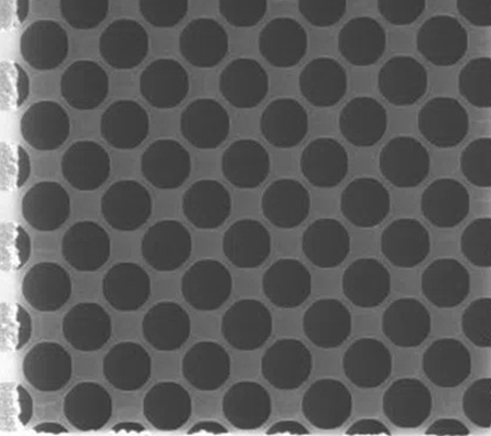
QUANTIFOIL® Holey Carbon Film supports with circular holes are used in a wide range of applications from materials science to molecular biology and biomedical imaging. The circular holes allow improved sample distribution and reduced background scatter due to the formation of thin, even layers of vitrified ice that support the particles of interest. Users can select from a wide range of holes depending on their sample characteristics and imaging modality:
- Small holes for high-resolution SPA of protein complexes;
- Larger holes and less carbon to maximise open viewing area for tomography and materials science;
- More Carbon and fewer holes for on-grid cell growth.
A Mix Box of 30 grids in popular sizes (QUANTIFOIL® R 1.2/1.3, R 2/1, R 3.5/1, S 7/2, Multi A and continuous Carbon) on Copper 300 mesh base grids is available to help select the optimum foil.
Did you know?
Our Carbon support films can be supplied on a number alternative meshes and finder grid formats for integrated methods and other applications.
Small hole geometries - in particular R 0.6/1 and R 1/1 - provide high density of holes if you are looking to design a high throughput, single shot per hole data collection. As described in:
Peck, Fay and Strauss. High-speed high-resolution data collection on a 200 keV cryo-TEM. IUCrJ 9: 243-252(2022)
In addition, smaller holes minimize ice thinning (or breakage) at the center. This promotes better distribution of large particles in the center of grids, and particularly of detergent-solubilized particles, where detergent causes additional thinning. A recent example is:
Kschonsak et al. Cryo-EM reveals an unprecedented binding site for NaV1.7 inhibitors enabling rational design of potent hybrid inhibitors. Elife 12: e84151 (2023)

Our most popular geometry is R 1.2/1.3. The holes are small enough to allow the formation of a thin, well-supported layer of ice, with the majority of the hole within the beam. Though R 1.2/1.3 is certainly the most popular option, similar geometries such as R 1/2, R 2/1 and R 2/2 are also well-suited for most applications, and should be considered during sample optimization. This geometry is available on Copper, Gold and other metal grids on a range of meshes including finder grids. As our most popular geometry, these grids are used in a wide range of applications including:
- Most commonly, single particle analysis to obtain high-resolution reconstructions of biological macromolecules:
Freda et al. Structural insights into the DNA recognition mechanism by the bacterial transcription factor PdxR. Nucleic Acid Res. 51: 8237-8254 (2023).
Zhao et al. Structure of a fungal 1,3-β-glucan synthase. Sci Adv 9: eadh7820 (2023).
Imai et al. Dynamically regulated two-site interaction of viral RNA to capture host translation initiation factor. Nat. Commun. 14: 4977 (2023).
- They are also used for cryo-electron tomography, FIB-milling and correlative microscopy (though larger hole sizes such as R 2/2 and R 2/1 are generally preferred for this:
Hu et al. Adeno-Associated Virus Receptor-Binding: Flexible Domains and Alternative Conformations through Cryo-Electron Tomography of Adeno-Associated Virus 2 (AAV2) and AAV5 Complexes. J. Virol. 96: e0010622 (2022).
Leistner et al. The in-tissue molecular architecture of β-amyloid pathology in the mammalian brain. Nat Commun. 14: 2833 (2023).
- One recent example of this geometry being used for more general imaging is:
Xian et al. Oral liposomal delivery of an activatable budesonide prodrug reduces colitis in experimental mice. Drug Delivery 30: 2183821 (2023).
- They are also used in materials and physical imaging in some contexts:
Aizawa et al. Enantioselectivity of discretized helical supramolecule consisting of achiral cobalt phthalocyanines via chiral-induced spin selectivity effect. Nat. Commun. 14: 4530 (2023).
If you'd like to learn more about the wide range of applications in which our most popular geometry is utilised you can:

While our small hole and R 1.2/1.3 geometries are ideal to maximize holes available for single shot-per-hole strategies, an increasingly popular way to increase throughput for cryoEM data collection is to use a "multi-shot" strategy, with more than one exposure per hole. This technique reduces the number of times that re-focusing is required by data collection, and therefore significantly increases data collection speed. The larger 2 μm hole geometries, R 2/1, R 2/2, or even R 2/4, are ideal for this collection strategy as they are large enough, in combination with fringe-free illumination, to easily accommodate multiple exposures per hole without pre-exposure of later positions during earlier shots.
The use of this data collection strategy is described in:
Weis and Hagen. Combining high throughput and high quality for cryo-electron microscopy data collection. Acta Cryst D76: 724-728 (2020).
An early example of its use was:
Peña et al. Substrate-engaged 26S proteasome structures reveal mechanisms for ATP-hydrolysis-driven translocation. Science 362: eaav0725 (2018).
More recent examples include:
Carbone et al. Time-resolved cryo-EM visualizes ribosomal translocation with EF-G and GTP. Nat. Commun. 12: 7236 (2021).
Carbone et al. ArfB can displace mRNA to rescue stalled ribosomes. Nat. Commun. 11: 5552 (2020).

The use of cryo-electron tomography (cryoET) and (plasma) focused ion beam (FIB)-milling, is a powerful technique for understanding the structure, dynamics and mechanism of proteins and complexes in situ in their native cellular environment. QUANTIFOIL® SiO2 foils offer a resilient, bio-compatible option that is ideal for FIB-milling and tomography, but our Carbon films are also a popular choice for this application as well. The necessity of tilting the stage means that grids with larger open viewing areas are preferred, in particular Gold 200 mesh. Larger hole geometries (R 2/2 and R 2/1) are favoured for the same reason, if only tomography is used. Where FIB-milling is employed, as excess support will be milled away, hole geometry is less important, and as cells tend to prefer larger areas of support, smaller hole sizes and more Carbon support is often chosen, such as R 1/4 and R 1.2/20.
A number of publications have provided recent descriptions of sample preparation for cryo-electron tomography. Including:
Dumoux et al. Cryo-plasma FIB/SEM volume imaging of biological specimens. eLife 12: e83623 (2023).
Lam and Villa. Practical approaches for cryo-FIB milling and applications for cellular cryo-electron tomography. Methods Mol Biol 2215: 49-82 (2021).
Turk and Baumeister. The promise and the challenges of cryo-electron tomography. FEBS Lett. 594: 3243-3261 (2020).
Recent examples of cryoET publications that reference the use of QUANTIFOIL® Carbon foils include:
Kaplan, Yao and Jensen. Structure and Assembly of the Proteus mirabilis Flagellar Motor by Cryo-Electron Tomography. Int. J. Mol. Sci. 24: 8292 (2023).
Chen et al. Visualizing the membrane disruption action of antimicrobial peptides by cryo-electron tomography. Nat. Commun. 14: 5464 (2023).
Seegar et al. Apilactobacillus kunkeei releases RNA-associated membrane vesicles and proteinaceous nanoparticles. Microlife 4: uqad037 (2023).
Micropatterning is a technique that can ensure cells grow in predictable locations on the grid surface, increasing the success of tomography and FIB-milling experiments.
The protocol for micropatterning is described in: Engel et al. Lattice micropatterning for cryo-electron tomography studies of cell-cell contacts. J. Struct. Biol. 213: 107791 (2021).
A recent examples of in situ cryoET utilizing micropatterning include:
Dow et al. Morphological control enables nanometer-scale dissection of cell-cell signaling complexes. Nat. Commun. 13: 7831 (2022).
Kim et al. Handling difficult cryo-ET samples: A study with primary neurons from Drosophila melanogaster. bioRxiv (2023).

Correlative Light and Electron Microscopy (CLEM) and Correlative Light X-ray Microscopy (CLXM) combine information from two or more different microscopies to provide a fuller understanding of a system. This can be particularly powerful when, for example, time-resolved data from single molecular fluorescence imaging is combined with high resolution in situ structural data from cryo-electron tomography. Biological cells often prefer more support, and focused ion beam (FIB) milling prior to tomography will remove unwanted materials, so geometries including R 1/4 and R 1.2/20 are often selected for this reason. Where FIB-milling will not be used, larger open viewing area geometries, such as R 2/2 or even R 3.5/1 are more appropriate.
Finder grids (where grid mesh squares are numbered) are popular to help identify similar locations on different microscopes. Quantifoil can provide both Carbon and SiO2 foils on a range of finder grids to facilitate integrative and correlative methodologies. A brochure is provided to help users select the optimum finder grid format for their work.
There are several examples of CLEM work-flows published, including:
Jun et al. Correlative microscopy for 3D structural analysis of dynamic interactions. J. Vis. Exp.: 50386 (2013).
A robust CLXM workflow is described in:
Okolo et al. Sample preparation strategies for efficient correlation of 3D SIM and soft X-ray tomography data at cryogenic temperatures. Nat. Protoc. 16: 2851-2885 (2021).
Some recent examples of publications featuring CLEM experiments are:
Soler Palacios et al. Growth hormone remodels the 3D-structure of the mitochondria of inflammatory macrophages and promotes metabolic reprogramming. Front Immunol. 14: 1200259 (2023).
Wozny et al. In situ architecture of the ER-mitochondria encounter structure. Nature 618: 188-192 (2023).
Dudek et al. Previously uncharacterized rectangular bacterial structures in the dolphin mouth. Nat. Commun. 14: 2098 (2023).

Our largest open viewing area round hole formats are R 3.5/1, with 3.5 μm holes separated by 1 μm support, and R 17/5, with 17 μm holes separated by 5 μm support. The largest open viewing area overall is the square hole format S 7/2. These larger open viewing areas are ideal for tomography, or applications with larger particles, such as fibrils or micelles. We also offer a range of larger holes sizes with more support that can be useful for similar applications.
Recent publications utilizing larger hole geometries include:
Yu et al. Membrane translocation process revealed by in situ structures of type II secretion system secretins. Nat Commun. 14: 4025 (2023).
Hernandez-Gonzalez et al. A succession of two viral lattices drives vaccinia virus assembly. Plos Biology 21: e3002005 (2023).
Zimmermann et al. ATP-induced conformational change of axonemal outer dynein arms revealed by cryo-electron tomography. EMBO J 42: e112466 (2023).

